Showing posts with label Things I've made. Show all posts

Friday, October 22, 2021

An Apollo Hatch

 Long before computer operated mills (CNC) all of this was done using "a meat computer"; the guy turning the handle, knew how far to turn it.

As a kid, I hung around my dads aerospace machine shop, and watched guys on old Bridgeport mills, turn blocks of metal into amazing mechanical shapes. 

The main hatch of the Apollo Command module, that took men to the moon, was a beautiful piece of mechanical art. Fabricated by guys like the ones who worked for my dad. These unassuming guys, in their plaid shirts, oil stained leather aprons, cigarette in their mouth and a cup of coffee on a nearby bench, created the millions of parts to America's Apollo Spacecraft, with no computer operated machines, just their skill and experience.

Know as the "The Unified Hatch", this was a 350 pound, quick opening "vault door". 

It was called the unified hatch, because the original design, was actually 3 separate hatches, all of which had to be opened by the astronaut, in order to exit the spacecraft. After the tragic accident of Apollo One, in which a fire developed so quickly, that opening these hatches was impossible, NASA required a new design that could be opened quicker.

The redesigned hatch could be opened in around 3 seconds, and get out of the spacecraft in less than 30 seconds. A great improvement over the 60-90 seconds for the original design. 

Utilizing 15 latches, a mechanical gearbox, a counterbalance system and a gaseous nitrogen operated piston, this was an incredible piece of engineering and machining. 

This is the hatch from Apollo 11, which is now on display in the Smithsonian's Air and Space Museum.

In early 2019, I was talking with one of my clients, who had purchased one of my replica Apollo spacesuits, about the amazing accomplishments of America's industry, in designing and creating the massive amount of technology and hardware for Mercury, Gemini and Apollo spacecraft, in only 9 years. We both were fascinated by the spacesuits the astronauts wore, but at some point in the conversation I brought upon the Command Module hatch as one of my favorite pieces from the spacecraft. He agreed and I mention how I had wanted one, just to hang on my wall, to showoff  the skill of the 1960's machinists I admired as a kid. He said it was one of his dreams as well, them paused, and asked, "do you think you could build one?" At first I thought, no way. Those guys were far more skilled at machining than I'll ever be, but then realized that much of their skill and experience is sort of "captured" in the computers that run CNC mills and lathes today. For 40 years, I have been building things for film, museums and some for aerospace clients, and I thought well you have figured out complex projects in the past, why not this.

I told my client, that I thought I could....but it would be very expensive. He asked how much. I gave him a ballpark, thinking I could wriggle out of telling him I could build this, and he said, OK, think about it and give me a formal quote.

Once I had the check in my hand, I realized there was no way of getting out of it. So, like with any project, you start by gathering images and information. Having spent 30 years building replica space hardware, I have become friends with a number of retired aerospace people, and collectors. I have built full size Lunar Modules, both interior and exterior, along with replica's of just about every spacesuit that has gone into space. But, I hadn't done anything from the Command Module before. Well I had to start somewhere, so I reached out to my usual sources. Information was slim, but I did manage to acquire some original drawings and spec sheets on the hatch, alone with some high quality images of the individual hardware elements. There was also an Apollo hatch near me in the California Science Center, which I have done work for. 

One big advantage I had (which had not occurred to me initially) was having grown up around the type of shop that built parts like this, I was recognizing machining details, edge treatments and surface finishes as I was looking at the photos.

Real Apollo hatch in
the California Science Center
Gearbox detail of the Apollo hatch in
the California Science Center

The original hatch locking system was mostly machined stainless steel, with the body of the hatch made in aluminum. Since the intent was to hang this on a wall, I wanted to reduce the weight as much as possible, while still keeping it in machined metal. I also wanted the latches to function. So I would have most of the hardware machined from aluminum, and experiment with various finishes in order to match the original hatch.
The parts where drawn in Solidworks, a complex 3D engineering software. I had had limited experience with Solidworks, and self taught, so I new this was going to seriously test my skills. I started with some of the simpler parts and 3d print test pieces. I got a email one day from a friend who is incredibly knowledgeable about the Apollo Luna Module, and he said he had been looking into a source for information on the hatch.

It turns out, Andrew Barth, and engineering student, working with Adam Savage (Myth busters fame), decided to scan the Smithsonian's hatch and build a replica. But, this replica was to be made by dozens of different artists around the US, and out of a wide range of materials. The model files were posted on the Smithsonian's site, under free license for anyone who wanted to print a copy for themselves. The files were all solid .STL files, and were not useful for machining a working replica, but like the photos and drawings I already had, they where a useful source for information to assist my Solidworks drawings. Also, since the files were intended to be 3d printed, there where many parts that grouped together multiple parts, and had cavities which could not have been machined.


In the end I did about 200 drawings in Solidworks. The parts were jobbed out to CNC machine shops and as I received them, I did some machining operations for minor corrections, and edge treatments. This is where my experience in my dad's shop came in handy. The parts needed to look like they had been machined and surface finished with 1960's aerospace conventions and standards. So I did dozens of tests and various parts in order to get the appearance of the parts correct. My client wanted an "as new", or "just flown" look, so I didn't want too much aging or surface patina.
While some parts of the real hatch are made from aluminum, the parts that needed to look like stainless steel, I had electroless Nickle plated and then tumbled to match the stainless steel look of the originals. I also sourced correct cruciform, high tolerance bolts, to match the original bolts used on the real hatch. (Some cost $25 each)

My replica of the Apollo "Unified" hatch.

I wanted the latches to function, and as an added feature, I powered them with a remote control servo, so with a press of a button, you can lock and unlock all 15 latches.


For the exterior my client wanted it to look just like the freshly return spacecraft. At first this was tricky, because the real hatch, looks a bit "Fake", with it discolored chrome "mylar" outer layer. In researching the original specifications of the lunar mission hatches, I learned they were covered in aluminized Kapton. Kapton is a plastic that has a very wide operating temperature, and is transparent amber in color. The "Gold Foil" you see on the outside of the Lunar Module, is neither, it's not gold, and it's not foil. What it is, is Kapton, that has been aluminized on one side, and because it's transparent yellow, when viewed from the other side, it appears gold. It turns out, the Kapton on the exterior of the Command Module (CM), is Kapton that has been aluminized on both sides, and the yellow discoloration on the recently reentered CM, is where the aluminum micro-thin coating has burned off.
Well, lucky me, because I just happen to have, original, double metalized Kapton film (found on eBay years ago). After coming up with ways to "burn" off the aluminum, it was nearly a perfect match to the original. 

Exterior of the replica hatch, mounted on the wall stand, with the ablated aluminized Kapton film.

The wall mount allows the replica hatch to be swung so either the inside or outside surface can be displayed.

I have made 5 of these, and have 3 still available. (as of this publish date) 

If interested, please visit, Orbital Surplus for more information. or email chris@orbitalsupplus.com


Sunday, May 27, 2018

Things I've made: Tale of the two Vendel helmets

    This is a project I did a number of years ago, but was recently asked about it, so I thought I'd post something about the helmets I made.
Years ago I made a pre-Viking age, or "Vendel" decorated helmet for a TV producer as a private commission.  At the time, I was pretty happy with it. It was only the second time I did "repousse', the tooling of metal. The first time was for the "Viking" box used to hold the Loki Mask in the movie "The Mask"
However, as time goes on, hopefully, one learns more, and sees things in a new light. As I became more educated in the Vendel period, the light came on, and I realized this helmet was not very good.
Now, of course, I was compelled to make one that was better. But my life is a busy one, and was many years before I would make the time to do this.

Finally,
just as I started gathering materials on the Vendel period together and planning what I would make, a friend who was managing my rental department, expressed his desire of owning one of these decorated helmets or "field crowns". Skip, who, was heavily into Viking history,  had been doing a great job running the department and I always felt I couldn't afford to pay him enough. I felt this would be a nice thank you. Plus, if he knew I was making one of these, he would be jealous, so I thought, I'll just make two!
This is how my life often goes; No time to build one of something, but two of them, I'll figure out how to do it. (Although, I'm still trying to figure out how to get those two Ferrari's!)
The trick was, how to keep Skip from discovering what I was planning.

The Vendel period is a modern scholarly classified age in Sweden from 550 to 790 AD. Many of the extant swords and helmets are highly decorated and had similarities to late Roman ridge helms.
There are around 26 helmets or helmet fragments that have been found across Scandinavia, Northern Europe and eastern Russia. I don't know how many swords have been found.
Finds from graves at Vendel and Valsgärde show that Uppland, or the east-central part of Sweden, was an important area during this time and many of these finds are very well documented.
Although detailed documentation was difficult to come by, back in 2004 when I started, but I did manage to find a couple of Swedish publications that had some excellent photos.
Eventually I decided to make a helmet for myself similar to the Valsgärde 5, but I had to find out what Skip fancied.  Skip is a stickler for authenticity and I had planned on letting him see what I was making for myself, but I needed to keep him in the dark about the second one for him, while still get feed back on what he was dreaming of. After some surreptitious questioning, I found out he always liked the Vendel 14 helmet.
Interestingly, when I showed him an image of the Vendel 14, as it is now in a museum, he said, no, not that one. As we flipped through the book, he spotted a drawing of the one to which he was referring. The helmet he had admired for all those years was an early archaeological drawing of what they thought the Vendel 14 helmet would look like, once it was removed from the dirt and rust in which it was entombed. Once it was cleaned and reconstructed however, it looked very little like this drawing. (This incorrect drawing is still being published as a depiction of the "Vendel 14" helmet.)
Skip was pretty bummed because he realized he was in love with a helmet that was not a real thing. But I pointed out, the drawing is in keeping with the style of other helmets that had been found and it was still a viable choice. I really hoped he agreed with my assessment, because I really didn't like the real Vendel 14 helm. (Although, now it's grown on me a bit) He did and so I continued my research and planning.
Valsgärde 5
Vendel 14


I would make the helmets from modern sheet steel, and since we were likely to use these in reenactment battles in Europe, I chose to make them in 1050 spring steel, so the steel could be hardened. This process was all pretty straight forward, although the lattice work on the Valsgärde 5 turned out to be a little tricky. I needed to make sure all of the small bands lined up nicely with each separate panel. (Now, new research I have found, suggests that these areas were covered with fabric, and not visible!)
The decoration was more unfamiliar to me, so that was the biggest hurdle on this project.

First, I had to find out how these were made in the period and then see if I had a way to make them with the skills and tools I had available to me. The main decorated panels were made of thin "foil" sheets of metal, pressed over bronze relief plates. The center crest seemed to be fabricated or cast and the eyebrows and crest terminals were cast. All of the helmets I have researched have some type of copper alloy for these decorations, but Skip wore tons of really nice silver Viking jewelry. So I planned to make his decorations with fine silver.
To save time, I came up with a technique of making the pressed decorative panels by using a etched magnesium plate. These were used for creating rubber stamps and in the printing profession. The advantage to the acid etched magnesium, is the magnesium cuts extremely fast with the correct acid, so fine details can be made right next to deep, large details. If you are interested in this process, here is a nice video on how these mag plates are made.
Once I drew the artwork, I scanned it into the computer and did some corrections and scaling. I then printed out full size artwork to check porportion and spaceing of the design elements.
I would need to test metal thickness for the finished foil plates and how the size and depth of the etching worked with this foil.
There were a lot of tests. But, eventually, I decided to use .005" fine silver and brass pressed into the mag plates. People have asked, why not Sterling Silver; Sterling is a harder alloy that contains  92.5% by weight of silver and 7.5% of other metals, usually copper, so it is harder. Fine silver is 99.9% silver, so it can be made softer. This turns out to be critical with my process. To impress the foil, I used wet leather and my 20 ton mold press. The wet tooling leather (flesh side down) was chosen over rubber, because the rubber acts as a "single surface" and would bridge certain fine detail. The wet leather on the other hand was more granular and pressed into these details nicely. Once the foils were pressed, I used small metal ball and spoon shaped tools to press or "sculp" more dimension into the foils by working the backside of each foil panel, while it was supported in pitch. Another element is the ribbed strips that boarder the panels. This was made by turning a rolling die on my lathe and rolling each strip through the mill. This of course required a few steps, annealing, straightening and re-annealing.

For the cast details I carved waxes instead of carving the mold from soft stone, like the originals had been made. Part of my job making props is to figure out techniques that can achieve a specific look, but can produce the item faster or in a way more familiar to my skill set.

Since Skips persona in the living history was more Viking then Vendel, I formed the fine silver eyebrow pieces from thick sheet and did punch decoration, which was more the style of Viking work in later centuries. These pieces were placed in pitch for support and I made a variety of steel punches with the needed shapes.

The other trick piece to make was the support for the mail drape across the back of each helm. This needed to be a hollow tube, curved in a semicircle, with a set of flanges sticking up, in order to fit the "tubes" to the lower rim of each helmet. In addition, each tubular section needed to have slices cut in at intervals in which to fit each ring on the top edge of the mail. The links of the mail are then held in place with a wire threaded through the links inside this tube. Nearly all the edges have a rolled boarder of brass or silver. This was fabricated by starting with strips, then pulling them through a draw die so they curl up like a tube, Once annealed, the can be formed around the edge of the plate.

The last task, was making rivets for the silver helmet, since I never found a source for silver rivets.

In the end, I finally did get both helmets completed. Here they are.


I told someone that these came as a kit: All flat material, no instructions and one of them was missing the rivets!....their response......"Where did you buy the kits?"

Thanks for looking.

Sunday, November 20, 2011

Work place noise attenuation

Sometimes I need to wear hearing protection and many times like others, want my own music. I don’t like earbuds because the either fall out or bother my ears and don’t cover my ear to help cut down on harsh shop noises. I like headphones, but they need to be light enough so when you bend over, they aren’t sliding around. I really like my Bose Quiet Comfort headphones. Their noise reduction quality is very good and of course the playback is great. They are light weight and comfortable. The only down side was the cord. I have tried cordless headphones, but I have to say, every pair I’ve used is worthless. They are heavy and the connection to the base is always cutting in and out. Even a Bluetooth unit in my pocket is intermittent. I hated record albums for the noise they had if everything wasn’t perfectly clean, so I was happy to embrace the digital age, so these wireless headphones just reminded me of the similar noise issues associated with vinyl. One day I realized that the Bose cord connection, which is a plug that can be removed from the headset, would be the perfect place to mount an IPod Nano.


Making a metal bracket and shortening the cord, I now had shop headphones that removed harsh shop noises, but let voices in and had no cord.

With this piece, I can now unplug the Nano and plug in the regular headphone cable and us my headphones for travel or other music sources.
I then needed a place to set these, along with my safety glasses, so when not in use, would be out of the way and safe. Pulling out a mold of my head (I know, don’t we all have one? It was made for a creature suit job many years ago) I was going to cast it in clear, but I was out of clear resin, so reaching into the mold, I smeared on some metallic powder and here is the result:

Friday, October 14, 2011

A 2011 Samsung Fridge becomes a 1930's fridge

My wife and I own a 1926 Arts & Crafts Bungalow and the previous owners "restored" it in 1980's "Home Depot style". I have re done the bedroom and laundry/ back hall area in a style inspired by the architects Greene & Greene, and now it's on to the kitchen and breakfast nook. We needed a new refrigerator, but we didn't like the idea of a modern appliance in a Craftsman style house. However, since my day job is making things look like things they are not, or replicating just about anything, it didn’t seem to hard to make a 2011 refrigerator look like a 1926 enameled Ice box.

We looked at many different modern efficient refrigerators and liked the Samsung. But since I hadn’t started on the restoration of the kitchen, we weren’t in any hurry to buy a new fridge. Well one day, we found one at Lowes on sale, because the handles where missing and the door had a small dent. An offer we couldn’t refuse! So, I needed to build a fridge. Here is what I started with:


I did some research and found many examples of white enameled Ice box's and refrigerators from the 20’s and 30’s.  Here are a couple of examples:


The plan was to add fake ice box doors to the front of the stainless fridge, with only the one over the ice maker a functional door. The others would be attached to the Samsung’s doors and when the handle was pulled, the whole Samsung door would open. I laid out the door proportions in Corel Draw and then cut ¾” MDF as patterns.  The doors where to be vacuum formed from 1/8 plastic about ½” high with a Coroplast filler.(Trade name for corrugated plastic material)  This Coroplast piece would keep the vacuum formed Icebox door panels stiff, without adding much weight to the fridge doors.

For my hardware, ebay seemed like a good source, but I couldn’t find just the right thing. So, I fabricated a handle in brass, based on a period one, but about twice as large and located the hinges from McMaster Carr. (A great source for many things) However, the hinges where $35 ea! I needed 11 of them and only 2 had to work. Well $385 for hinges was a bit to steep, even if we had saved double that on the “damaged” fridge. Luckily, I have a spin caster for “white metal” pewter casting, so I made my own.
This process entails "pressing" a rubber mold of your master parts in a vulcanizing press. This press heats the rubber to about 300 f and subjects the raw hot rubber to about 1500 psi. Once the mold heat cures (about an hour),  it’s placed in a spin caster and the molten pewter (500 f.) is ladled into the top of the machine which pours into the spinning mold. 60 seconds later, you have cast metal parts. This is a very common way to make many different types of inexpensive metal items. Here is a photo of the hardware and the rubber mold:


Each piece of hardware was attached with stainless machine screws with an “Oval” style head. This is a counter sunk screw with a slightly domed head. Since Phillips screws, invented by Henry F. Phillips, were not in use until 1937, slotted style was chosen. Each screw, threads into a “Riv-nut”, a “pop rivet” style of threaded insert that is commonly used in sheet metal applications. This riv-nut provides more robust threads in a thin sheet skin.

Here is the assembled fridge with plastic door panels and cast hardware:

 The door over the Ice maker has a vacuum formed inner panel and is bonded to the outer panel with a 3/8” wood filler to make a complete door that has a nice feel and weight to it. Since this was the only working door, I wanted it to feel more like the type of insulated metal door that would be on an original fridge.

Once I had all the hardware deburred and prepped I sent it to my friends at F&H plating for a brushed nickel finish. The fridge was sanded, masked and given a white automotive paint finish.

With the newly plated hardware the 2011 Samsung was transformed into a 1930’s(ish) fridge.


The last touch will be a “Manufacturers plate” added to the gap between the left hand doors. (A printed place holder can be seen in the photo.)

This gap between doors seems to be a common thing on many of these old fridges and I assume it’s because there is some plumbing elements there. Well since my door layout is cosmetic, with the exception of the door covering the ice maker, I incorporated this gap in the design with the intention of adding the plate. The manufacturers plate is acid etched in magnesium, using a process used for making rubber stamps. here is the finished badge.


Update:

Per request, here is a shot of the fridge with the water/ice door open. It also shows the sheet metal fascia at the bottom, this replaces the original plastic one and facilitates the legs to be added. Most of these old ice boxes and coolers had legs and were raised off the floor. Because we have the fridge located in a part of the kitchen that steps down, raising it was essential to allow the righthand door to fully open. In addition, because both my wife and I are above average height, raising the fridge is perfect, it turns out it is a much better height for us.
Here is an update, with the fully restored kitchen:


Wednesday, April 6, 2011

Cupboard part 2

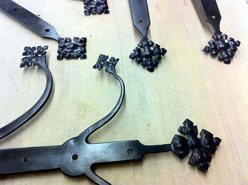
To make the hinge part, I made a press plate and using a vise;

I pressed a pin into the groove,

then heated the unformed part of the strap and closed them over the pin. Same for the other side and presto, hinges.
The decorations at the ends where made by first thinning the metal to about 16ga. And then using punches, I punched the "bumps" in from the back on a piece of lead. To finish the design, I made cuts with dykes, then using a torch to heat the steel to yellow hot a few times with a quench and wire bush in between, I was able to burn out the thinner cut edges left by the dykes and open up the cuts to match the look of the original.  I then tuned them up a little with a file and blackened them and applied a paste wax.


After making those I made the lock plates, although I stopped short of actually making locks for them.
For the final assembly of the cabinet, I needed dowel pins. Using a technique I learned from a traditional rake maker, I sharpened a steel tube that had the correct inside diameter and rough cut pine chunks and drove them through the sharpened tube. The result is nicely cut round pegs. These where driven into drilled hole bisecting the tennons and side panels. All glued with white glue.
The cupboard was made from Pine, but I wanted a darker look and so I used Mahogany leather dye and with an atomizer, sprayed the dye onto the finished cabinet. I then applied a urethane clear with a spray gun.
In order to save some time, I ordered some nails from  www.tremontnail.com (thanks for the tip) and tuned them up a little and finished the cupboard. Here is the result with the Keg “jockey box” on top.


However, I had so much fun making the first set of hinges, I made some others for some chest I bought at Pennsic 15 years ago. They looked too “modern” so I re-cut the lids and am going to add the fancy hinges. I may add these same “sprays” to the front and sides.

Wednesday, March 23, 2011

A 15th Century Cupboard

One of the things I was suppose to have for last year’s Pennsic was a correct period table for the “jockey box” keg in my house. In trade for a bunch of old furniture, I had arranged with a local furniture restorer/ maker to make it for me. He flaked. So I am making it myself. Here is what I was looking at. I may do some of the carving.

Saturday I did a drawing in Corel Draw and Sunday morning picked up some pine boards. Originally I had planned to “throw it together”, but I decided not to be so lazy and make it a little nicer. Now I’m not a wood worker, So if Peter Follansbee reads this, please don’t be too harsh. For those of you who don’t know Mr. Follansbee’s work, you should check out his blog, some amazing stuff. http://pfollansbee.wordpress.com/
Anyway, I don’t have a lot of woodworking tools and to cut my mortises, I used my Bridgeport mill. Nearly all of the other work was completed using a table saw, band saw, router and a compound miter saw. Working about 6 hours Sunday I got the frame completed. The board on top is a just for size. The real top is on the table in the background drying.

Monday morning I rabbitted the inside and lower shelves as well as the inside walls of the cabinet.  Here is the cupboard, just pressed together.  I still need to clean up the shoulders of the tenons before I glue it together and of course flush cut the tenons and sand them. But I'm pretty happy with the way it looks.

I now needed hardware. I have a very nice book that is filled with 19th C. etchings of 12th to 17th century ironwork. From latches and locks to gates and candlesticks. (I will get the title and publishing info and post it) I used a couple of examples in there to create the hinge design. I spent today making hinges.
Again, I first did a drawing in Corel and using 3M 77 spray adhesive I glued the printout to some 13 gauge mild steel. Using a band saw I rough cut these out.

I then center punched the holes and drilled them. Then did the final cut. Once cut, I sanded the profiles with a Burr King.

 The decorations at the ends where made by making cuts with dykes, then using a torch to heat the steel to yellow hot a few times with a quench and wire bush in between, I was able to burn out the thinner metal left by the dykes and open up the cuts to match the look of the original.
I then tuned them up a little with a file and blackened them and applied a paste wax. They are currently “tacked on” with small screws, but they will be eventually held with clinched nails. (which I’ll have to make)


Here are all 4 on the cupboard

 I still have the latch plates to make, but here is the cupboard in is designated place in the house.